XHGG501XLocalizzatore di guasti ai cavi
Localizzatore avanzato di guasti nei cavi con tecnologia Time Domain Reflectometry (TDR) per test precisi della distanza dei guasti con risoluzione minima leader del settore di 0,1 m.
Questo tester per guasti ai cavi realizza separatamente il campionamento del cavo trifase ABC e la forma d'onda di campionamento viene visualizzata sullo schermo contemporaneamente, in modo che la forma d'onda del cavo trifase possa essere confrontata. Lo strumento ha le funzioni di velocità di campionamento degli impulsi di uscita adattiva e analisi automatica della forma d'onda e l'applicazione è semplice.
Caratteristiche del prodotto
| Durata massima della prova | non meno di 50 km |
| Velocità di campionamento | 10 MHz, 20 MHz, 50 MHz, 100 MHz, 200 MHz |
| Larghezza dell'impulso | 1us, 0,75us, 0,5us, 0,2us, 0,1us |
| Ampiezza dell'impulso | 400 V |
- Tecnologia Time Domain Reflectometry (TDR).
- Localizzazione precisa dei guasti nei cavi
 Capacità di test a distanza
- Risoluzione minima 0,1 m
- Funzionalità diagnostica intelligente
Principio di funzionamento
Il tester per guasti ai cavi adotta il principio di prova del metodo delle onde viaggianti:
1. Metodo dell'onda viaggiante: quando l'onda radio viene trasmessa nella linea di trasmissione, se la linea di trasmissione non è uniforme, cioè l'impedenza caratteristica di un punto nella linea di trasmissione cambia, quando l'onda radio viene trasmessa al punto, oltre a continuare a trasmettere al carico, produrrà anche trasmissione inversa e ritornerà all'estremità del test, chiamiamo trasmissione inversa dell'onda riflessa, il fenomeno dell'onda che produce trasmissione inversa è chiamato fenomeno di riflessione dell'onda. La cosiddetta onda viaggiante si riferisce al nome generale di onda incidente e onda riflessa.
2, quando l'onda radio viene trasmessa sulla linea di trasmissione, la polarità dell'eco nel punto di cortocircuito è opposta alla polarità dell'impulso emesso e la polarità dell'eco nel punto di interruzione (incluso il terminale del cavo) è la stessa della polarità dell'impulso emesso. Utilizzando il metodo a impulsi, lo strumento può facilmente determinare la distanza tra il punto di guasto e l'estremità del test in base alla polarità dell'eco.
3. Il tester per guasti ai cavi applica un segnale a impulsi a bassa tensione al cavo in prova e il segnale a impulsi genera un segnale riflesso attraverso il punto di guasto del cavo. Il tester per guasti ai cavi elabora il segnale riflesso e presenta un diagramma della forma d'onda. La distanza grossolana del guasto del cavo in prova viene determinata analizzando la forma d'onda riflessa.
Il metodo di cablaggio è il seguente: utilizzare una singola linea Q per collegare l'"interfaccia di campionamento" del tester per guasti ai cavi alla linea di fase difettosa e allo strato di schermatura del cavo. Il cablaggio degli impulsi a bassa tensione è mostrato nella figura seguente.
Nota: durante il test è necessario verificare che non vi sia elettricità immagazzinata nel corpo del cavo.
Passo 1: Bloccare la linea del segnale per testare la fase A. Anche la selezione della fase di test dell'interfaccia corrispondente è impostata sulla fase A. Quindi fare clic sul pulsante campiona/mantieni sull'interfaccia per accedere allo stato di campionamento. Osservare la forma d'onda di campionamento. Se pensi che il sla forma d'onda di amplificazione è buona, fare clic sul pulsante campione/mantieni per entrare nello stato di attesa per l'analisi della forma d'onda. Fare riferimento all'esempio "Forma d'onda".-Analizzare le forme d'onda.
Passaggio 2: fissare la linea del segnale per testare la fase B. Ripetere il primo passaggio del processo di test.
Passaggio 3: fissare la linea del segnale per testare la fase C. Ripetere il primo passaggio del processo di test.
Una volta completato il test in tre fasi di cui sopra, l'interfaccia visualizza contemporaneamente le forme d'onda del test a impulsi del cavo trifase.

 Il tuo messaggio deve contenere da 20 a 3000 caratteri!
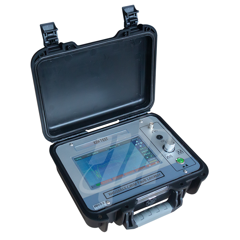
Rating complessivo
Rappresentazione del rating
Di seguito è riportata la distribuzione di tutte le valutazioniTutte le recensioni